E15R02P15
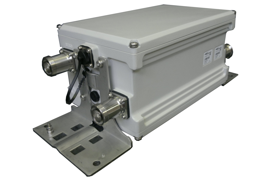
Tower Mounted Amplifier, Dual GSM SB 900 MHz with AISG
Specifications
Product classification
| Product Type | 1-BTS:1-ANT (Uniplex) | Tower mounted amplifier |
General specifications
| Color | Gray |
| Modularity | 2-Twin |
| Mounting | Pole | Wall |
| Mounting Pipe Hardware | Band clamps (2) |
| RF Connector Interface | 7-16 DIN Female |
| RF Connector Interface Body Style | Long neck |
Dimensions
| Height | 260 mm | 10.236 in |
| Width | 170 mm | 6.693 in |
| Depth | 140 mm | 5.512 in |
| Ground Screw Diameter | 6 mm | 0.236 in |
| Mounting Pipe Diameter Range | 40–160 mm |
Outline drawing
| Click on image to enlarge. |

Electrical specifications
| License Band, LNA | CEL 900 |
Electrical specifications, dc power/alarm
| dc Switching/Redundancy | Yes |
| Lightning Surge Current | 5 kA |
| Lightning Surge Current Waveform | 8/20 waveform |
| Operating Current at Voltage | 100 mA @ 12 Vdc |
| Operating Current Tolerance | ±20 mA |
| Voltage | 7–30 Vdc |
| Alarm Current, CWA Mode | 185 mA ±15 mA |
Electrical specifications, aisg
| AISG Connector | 8-pin DIN Female |
| AISG Connector Standard | IEC 60130-9 |
| Protocol | AISG 2.0 |
| Voltage, AISG Mode | 10–30 Vdc |
Electrical specifications
| Sub-module | 1 | 2 |
| Branch | 1 |
| Port Designation | ANT |
| License Band | CEL 900, LNA |
Electrical specifications, rx uplink
| Frequency Range, MHz | 898–915 |
| Bandwidth, MHz | 17.00 |
| Gain, nominal, dB | 13.0 |
| Gain Tolerance, dB | ±1 |
| Noise Figure, maximum, dB | 1.8 |
| Noise Figure, typical, dB | 1.5 |
| Output IP3, minimum, dBm | 23 |
| Return Loss, minimum, dB | 18 |
| Insertion Loss - Bypass Mode, typical, dB | 2.8 |
| Return Loss - Bypass Mode, typical, dB | 18 |
| TX Band Rejection, minimum, dB | 80 |
Electrical specifications, tx downlink
| Frequency Range, MHz | 943–960 |
| Bandwidth, MHz | 17.00 |
| Insertion Loss, maximum, dB | 0.60 |
| Return Loss, minimum, dB | 18 |
| RX Band Rejection, minimum, dB | 70 |
| Input Power, RMS, maximum, W | 200 |
| Input Power, PEP, maximum, W | 5,000 |
| 3rd Order PIM, maximum, dBc | -155 |
| 3rd Order PIM Test Method | Two +43 dBm carriers |
| 5th Order PIM, maximum, dBc | -163 |
| 5th Order PIM Test Method | Two +43 dBm carriers |
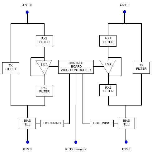
Block diagram
| Click on image to enlarge. |
Material specifications
| Finish | Painted |
Environmental specifications
| Operating Temperature | -40 °C to +65 °C (-40 °F to +149 °F) |
| Relative Humidity | Up to 100% |
| Corrosion Test Method | IEC 60068-2-11, 30 days |
| Ingress Protection Test Method | IEC 60529:2001, IP67 |
Packaging and weights
| Included | Mounting hardware |
| Weight, net | 8 kg | 17.637 lb |
Regulatory compliance/certifications
| Agency | Classification |
| ISO 9001:2015 | Designed, manufactured and/or distributed under this quality management system |
Product classification
| Product Type | 1-BTS:1-ANT (Uniplex) | Tower mounted amplifier |
General specifications
| Color | Gray |
| Modularity | 2-Twin |
| Mounting | Pole | Wall |
| Mounting Pipe Hardware | Band clamps (2) |
| RF Connector Interface | 7-16 DIN Female |
| RF Connector Interface Body Style | Long neck |
Dimensions
| Height | 260 mm | 10.236 in |
| Width | 170 mm | 6.693 in |
| Depth | 140 mm | 5.512 in |
| Ground Screw Diameter | 6 mm | 0.236 in |
| Mounting Pipe Diameter Range | 40–160 mm |
Electrical specifications
| License Band, LNA | CEL 900 |
Electrical specifications, dc power/alarm
| dc Switching/Redundancy | Yes |
| Lightning Surge Current | 5 kA |
| Lightning Surge Current Waveform | 8/20 waveform |
| Operating Current at Voltage | 100 mA @ 12 Vdc |
| Operating Current Tolerance | ±20 mA |
| Voltage | 7–30 Vdc |
| Alarm Current, CWA Mode | 185 mA ±15 mA |
Electrical specifications, aisg
| AISG Connector | 8-pin DIN Female |
| AISG Connector Standard | IEC 60130-9 |
| Protocol | AISG 2.0 |
| Voltage, AISG Mode | 10–30 Vdc |
Electrical specifications
| Sub-module | 1 | 2 |
| Branch | 1 |
| Port Designation | ANT |
| License Band | CEL 900, LNA |
Electrical specifications, rx uplink
| Frequency Range, MHz | 898–915 |
| Bandwidth, MHz | 17.00 |
| Gain, nominal, dB | 13.0 |
| Gain Tolerance, dB | ±1 |
| Noise Figure, maximum, dB | 1.8 |
| Noise Figure, typical, dB | 1.5 |
| Output IP3, minimum, dBm | 23 |
| Return Loss, minimum, dB | 18 |
| Insertion Loss - Bypass Mode, typical, dB | 2.8 |
| Return Loss - Bypass Mode, typical, dB | 18 |
| TX Band Rejection, minimum, dB | 80 |
Electrical specifications, tx downlink
| Frequency Range, MHz | 943–960 |
| Bandwidth, MHz | 17.00 |
| Insertion Loss, maximum, dB | 0.60 |
| Return Loss, minimum, dB | 18 |
| RX Band Rejection, minimum, dB | 70 |
| Input Power, RMS, maximum, W | 200 |
| Input Power, PEP, maximum, W | 5,000 |
| 3rd Order PIM, maximum, dBc | -155 |
| 3rd Order PIM Test Method | Two +43 dBm carriers |
| 5th Order PIM, maximum, dBc | -163 |
| 5th Order PIM Test Method | Two +43 dBm carriers |
Material specifications
| Finish | Painted |
Environmental specifications
| Operating Temperature | -40 °C to +65 °C (-40 °F to +149 °F) |
| Relative Humidity | Up to 100% |
| Corrosion Test Method | IEC 60068-2-11, 30 days |
| Ingress Protection Test Method | IEC 60529:2001, IP67 |
Packaging and weights
| Included | Mounting hardware |
| Weight, net | 8 kg | 17.637 lb |
| Click on image to enlarge. |
| Click on image to enlarge. |
Regulatory compliance/certifications
| Agency | Classification |
| ISO 9001:2015 | Designed, manufactured and/or distributed under this quality management system |
Installation & videos
Installation instruction
Filter Products – Designed for PIM Excellence

Filter Products – Designed for PIM Excellence
Documentation & downloads