E15R02P10
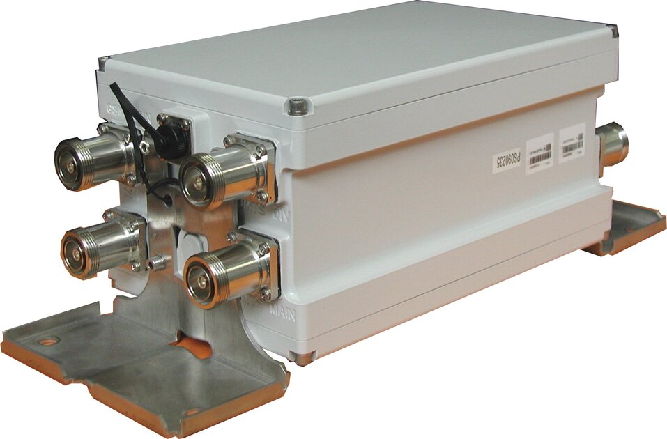
SpectrumShare Active Filter for GSM 900 and UMTS 900
Specifications
Product classification
| Product Type | Diplexer |
General specifications
| AISG Connector | 8-pin DIN Female, circular |
| AISG Connector Standard | IEC 60130-9 |
| Connector Interface | 7-16 DIN Female |
| Connector Interface Style | Long neck |
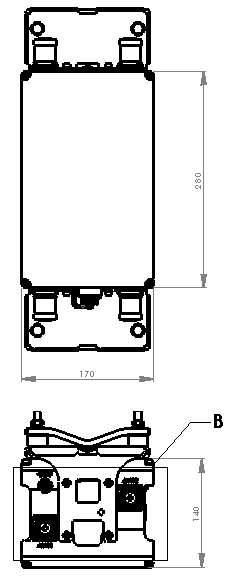
Dimensions
| Height | 280 mm | 11.024 in |
| Width | 140 mm | 5.512 in |
| Depth | 170 mm | 6.693 in |
Outline drawing
| Click on image to enlarge. |
Electrical specifications
| Input RF CW Power, no damage, maximum | 43 dBm @ 1 min |
| Failure Current Consumption | 185 mA ±10 mA @ 10–18 V |
| Lightning Protection | dc Ground |
| Lightning Surge Current | 5 kA |
| Lightning Surge Current Waveform | 8/20 waveform |
| Operating Current at Voltage | 100 mA ±10 mA @ 10–12 V | 140 mA ±15 mA @ 12 V |
| Overcurrent Protection | 2 A |
| Overcurrent Protection Tolerance | ±0.1 A |
| Power Consumption, maximum | 2 W |
| Signaling Interface at Frequency | 3 dBm @ 2,176 MHz |
| Signaling Interface Tolerance | ±2 dBm |
| Voltage | 0–48 V, survival | 7–30 V, operational |
Electrical specifications, rx (uplink)
| Filter Attenuation, minimum | 45 dB |
| Frequency Band | 880 – 915 MHz |
| Gain | 12 dB |
| Gain Ripple, maximum, specific | 1 dB (UMTS diversity) | 1.5 dB (GSM main) |
| Gain Tolerance | ±1 |
| Group Delay Variation at Frequency, maximum | 10 ns @ 240.00 MHz | 70 ns @ 5.00 MHz |
| Insertion Loss Ripple, Bypass Mode, specific | 0.8 dB (UMTS diversity) | 1.3 dB (GSM main) |
| Insertion Loss, Bypass Mode, typical | 6 dB |
| Return Loss, Bypass Mode, minimum | 17 dB |
| Return Loss, minimum | 17 dB |
| Isolation, minimum, specific | 20 dB (GSM main to UMTS diversity) | 36 dB (GSM main to GSM diversity) | 36 dB (GSM main to UMTS main) | 36 dB (UMTS diversity to GSM diversity) | 36 dB (UMTS diversity to UMTS main) |
| License Band | UMTS 900 |
| Noise Figure, Full Band at Temperature, typical | 1.70 dB @ 25 °C |
| Noise Figure, Mid Band at Temperature, typical | 1.20 dB @ 25 °C |
| Output 1 dB Compression Point, minimum | 10 dBm |
| Output IP3, minimum | 23 dBm |
| Port Designation | Antenna port 1 |
| Total Group Delay, maximum | 180 ns |
Electrical specifications 2, rx (uplink)
| Filter Attenuation, minimum | 45 dB |
| Frequency Band | 880 – 915 MHz |
| Gain | 12 dB |
| Gain Ripple, maximum, specific | 1 dB (UMTS diversity) | 1.5 dB (GSM main) |
| Gain Tolerance | ±1 |
| Group Delay Variation at Frequency, maximum | 10 ns @ 240.00 MHz | 70 ns @ 5.00 MHz |
| Isolation, minimum, specific | 20 dB (GSM diversity to UMTS main) | 36 dB (GSM diversity to GSM main) | 36 dB (GSM diversity to UMTS diversity) | 36 dB (UMTS main to GSM main) | 36 dB (UMTS main to UMTS diversity) |
| License Band | GSM |
| Noise Figure, Full Band at Temperature, typical | 1.70 dB @ 25 °C |
| Noise Figure, Mid Band at Temperature, typical | 2.00 dB @ 25 °C |
| Output 1 dB Compression Point, minimum | 10 dBm |
| Output IP3, mimimum | 23 dBm |
| Port Designation | Antenna port 2 |
| Total Group Delay, maximum | 180 ns |
| Insertion Loss Ripple, Bypass Mode, specific | 0.8 dB (GSM diversity) | 1.3 dB (UMTS main) |
| Insertion Loss, Bypass Mode, typical | 6 dB |
| Return Loss, Bypass Mode, minimum | 17 dB |
| Return Loss, minimum | 17 dB |
Electrical specifications, tx (downlink)
| 3rd Order IMD Test Method | Two +43 dBm carriers |
| 3rd Order IMD, specific | -107 dBm (antenna port 1) | -95 dBm (GSM main) |
| Filter Attenuation, minimum | 50 dB |
| Frequency Band | 925 – 960 MHz |
| Group Delay Variation at Frequency, maximum | 65 ns @ 5.00 MHz |
| License Band | GSM |
| Input Power, PEP, maximum | 5000 W |
| Total Group Delay, maximum | 110 ns |
| Insertion Loss Ripple, maximum | 0.7 dB |
| Insertion Loss, maximum | 0.85 dB |
| Return Loss, minimum | 18 dB |
Electrical specifications 2, tx (downlink)
| 3rd Order IMD Test Method | Two +43 dBm carriers |
| 3rd Order IMD, specific | -107 dBm (antenna port 2) | -95 dBm (UMTS main) |
| Filter Attenuation, minimum | 80 dBm |
| Frequency Band | 925 – 960 MHz |
| Group Delay Variation at Frequency, maximum | 65 ns @ 5.00 MHz |
| Input Power, PEP, maximum | 5000 W |
| Insertion Loss Ripple, maximum | 0.7 dB |
| Insertion Loss, maximum | 0.85 dB |
| License Band | UMTS 900 |
| Return Loss, minimum | 18 dB |
| Total Group Delay, maximum | 110 ns |
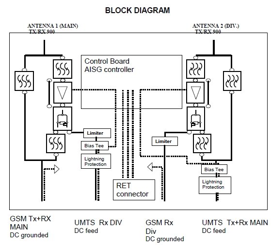
Block diagram
| Click on image to enlarge. |
Environmental specifications
| Operating Temperature | -40 °C to +65 °C (-40 °F to +149 °F) |
| Ingress Protection Test Method | IEC 60529:2001, IP67 |
Packaging and weights
| Weight, without mounting hardware | 8 kg | 17.637 lb |
Regulatory compliance/certifications
| Agency | Classification |
| ISO 9001:2015 | Designed, manufactured and/or distributed under this quality management system |
Product classification
| Product Type | Diplexer |
General specifications
| AISG Connector | 8-pin DIN Female, circular |
| AISG Connector Standard | IEC 60130-9 |
| Connector Interface | 7-16 DIN Female |
| Connector Interface Style | Long neck |
Dimensions
| Height | 280 mm | 11.024 in |
| Width | 140 mm | 5.512 in |
| Depth | 170 mm | 6.693 in |
Electrical specifications
| Input RF CW Power, no damage, maximum | 43 dBm @ 1 min |
| Failure Current Consumption | 185 mA ±10 mA @ 10–18 V |
| Lightning Protection | dc Ground |
| Lightning Surge Current | 5 kA |
| Lightning Surge Current Waveform | 8/20 waveform |
| Operating Current at Voltage | 100 mA ±10 mA @ 10–12 V | 140 mA ±15 mA @ 12 V |
| Overcurrent Protection | 2 A |
| Overcurrent Protection Tolerance | ±0.1 A |
| Power Consumption, maximum | 2 W |
| Signaling Interface at Frequency | 3 dBm @ 2,176 MHz |
| Signaling Interface Tolerance | ±2 dBm |
| Voltage | 0–48 V, survival | 7–30 V, operational |
Electrical specifications, rx (uplink)
| Filter Attenuation, minimum | 45 dB |
| Frequency Band | 880 – 915 MHz |
| Gain | 12 dB |
| Gain Ripple, maximum, specific | 1 dB (UMTS diversity) | 1.5 dB (GSM main) |
| Gain Tolerance | ±1 |
| Group Delay Variation at Frequency, maximum | 10 ns @ 240.00 MHz | 70 ns @ 5.00 MHz |
| Insertion Loss Ripple, Bypass Mode, specific | 0.8 dB (UMTS diversity) | 1.3 dB (GSM main) |
| Insertion Loss, Bypass Mode, typical | 6 dB |
| Return Loss, Bypass Mode, minimum | 17 dB |
| Return Loss, minimum | 17 dB |
| Isolation, minimum, specific | 20 dB (GSM main to UMTS diversity) | 36 dB (GSM main to GSM diversity) | 36 dB (GSM main to UMTS main) | 36 dB (UMTS diversity to GSM diversity) | 36 dB (UMTS diversity to UMTS main) |
| License Band | UMTS 900 |
| Noise Figure, Full Band at Temperature, typical | 1.70 dB @ 25 °C |
| Noise Figure, Mid Band at Temperature, typical | 1.20 dB @ 25 °C |
| Output 1 dB Compression Point, minimum | 10 dBm |
| Output IP3, minimum | 23 dBm |
| Port Designation | Antenna port 1 |
| Total Group Delay, maximum | 180 ns |
Electrical specifications 2, rx (uplink)
| Filter Attenuation, minimum | 45 dB |
| Frequency Band | 880 – 915 MHz |
| Gain | 12 dB |
| Gain Ripple, maximum, specific | 1 dB (UMTS diversity) | 1.5 dB (GSM main) |
| Gain Tolerance | ±1 |
| Group Delay Variation at Frequency, maximum | 10 ns @ 240.00 MHz | 70 ns @ 5.00 MHz |
| Isolation, minimum, specific | 20 dB (GSM diversity to UMTS main) | 36 dB (GSM diversity to GSM main) | 36 dB (GSM diversity to UMTS diversity) | 36 dB (UMTS main to GSM main) | 36 dB (UMTS main to UMTS diversity) |
| License Band | GSM |
| Noise Figure, Full Band at Temperature, typical | 1.70 dB @ 25 °C |
| Noise Figure, Mid Band at Temperature, typical | 2.00 dB @ 25 °C |
| Output 1 dB Compression Point, minimum | 10 dBm |
| Output IP3, mimimum | 23 dBm |
| Port Designation | Antenna port 2 |
| Total Group Delay, maximum | 180 ns |
| Insertion Loss Ripple, Bypass Mode, specific | 0.8 dB (GSM diversity) | 1.3 dB (UMTS main) |
| Insertion Loss, Bypass Mode, typical | 6 dB |
| Return Loss, Bypass Mode, minimum | 17 dB |
| Return Loss, minimum | 17 dB |
Electrical specifications, tx (downlink)
| 3rd Order IMD Test Method | Two +43 dBm carriers |
| 3rd Order IMD, specific | -107 dBm (antenna port 1) | -95 dBm (GSM main) |
| Filter Attenuation, minimum | 50 dB |
| Frequency Band | 925 – 960 MHz |
| Group Delay Variation at Frequency, maximum | 65 ns @ 5.00 MHz |
| License Band | GSM |
| Input Power, PEP, maximum | 5000 W |
| Total Group Delay, maximum | 110 ns |
| Insertion Loss Ripple, maximum | 0.7 dB |
| Insertion Loss, maximum | 0.85 dB |
| Return Loss, minimum | 18 dB |
Electrical specifications 2, tx (downlink)
| 3rd Order IMD Test Method | Two +43 dBm carriers |
| 3rd Order IMD, specific | -107 dBm (antenna port 2) | -95 dBm (UMTS main) |
| Filter Attenuation, minimum | 80 dBm |
| Frequency Band | 925 – 960 MHz |
| Group Delay Variation at Frequency, maximum | 65 ns @ 5.00 MHz |
| Input Power, PEP, maximum | 5000 W |
| Insertion Loss Ripple, maximum | 0.7 dB |
| Insertion Loss, maximum | 0.85 dB |
| License Band | UMTS 900 |
| Return Loss, minimum | 18 dB |
| Total Group Delay, maximum | 110 ns |
Environmental specifications
| Operating Temperature | -40 °C to +65 °C (-40 °F to +149 °F) |
| Ingress Protection Test Method | IEC 60529:2001, IP67 |
Packaging and weights
| Weight, without mounting hardware | 8 kg | 17.637 lb |
| Click on image to enlarge. |
| Click on image to enlarge. |
Regulatory compliance/certifications
| Agency | Classification |
| ISO 9001:2015 | Designed, manufactured and/or distributed under this quality management system |
Installation & videos
Installation instruction
Filter Products – Designed for PIM Excellence

Filter Products – Designed for PIM Excellence
Documentation & downloads