NHHSS-65B-HGT-R3B
4-port Next Generation PerforMax™ sector antenna, 2x 698–896, 4x 1695–2360 and 4x 3300-4000 MHz, 65° HPBW, 3x RETs and 2x SBTs.

Features and benefits
- Antenna optimized for higher gain with superior radiation efficiency
- Powered by Andrew's SEED® technology (Sustainable Energy Efficient Design)
- Designed to reduce SUB 1 alarm triggers with pattern consistency between low band, mid band and high band
- Superior patterns for enhanced interference mitigation resulting in improved SINR, higher throughput, and more capacity
- Best in class PIM immunity
- Interleaved dipole technology results into an attractive, low wind load mechanical package
- Internal SBTs allow remote RET control from the radio over the RF jumper cable
- Ideal for deploying low band, mid-band and CBRS/C-Band in flagpoles and concealment solutions
- Internal multiplexing reduces cable count from 10 cables to 4 cables per antenna, saving space on flag poles and reducing wind load on other applications
Specifications
General specifications
| Antenna Type | Sector |
| Band | Multiband |
| Color | Light Gray (RAL 7035) |
| Grounding Type | RF connector inner conductor and body grounded to reflector and mounting bracket |
| Performance Note | Outdoor usage |
| Radome Material | Fiberglass, UV resistant |
| Radiator Material | Low loss circuit board |
| Reflector Material | Aluminum |
| RF Connector Interface | 4.3-10 Female |
| RF Connector Location | Bottom |
| RF Connector Quantity, total | 4 |
Remote electrical tilt (ret) information
| RET Hardware | CommRET v2 |
| RET Interface | 4x 8 pin connector as per IEC 60130-9 Daisy chain in: Male / Daisy chain out: Female Pin3: RS485A(AISG_B), Pin5: RS485B(AISG_A), Pin6: DC 10~30V, Pin7: DC_ Return |
| RET Interface, quantity | 2 female | 2 male |
| Input Voltage | 10–30 Vdc |
| Internal Bias Tee | Port 1 | Port 3 |
| Internal RET | High band (1) | Low band (1) | Mid band (1) |
| Power Consumption, active state, maximum | 10 W |
| Power Consumption, idle state, maximum | 2 W |
| Protocol | 3GPP/AISG 2.0 |
Dimensions
| Width | 301 mm | 11.850 in |
| Depth | 181 mm | 7.126 in |
| Length | 1978 mm | 77.874 in |
| Net Weight, without mounting kit | 27.2 kg | 59.966 lb |
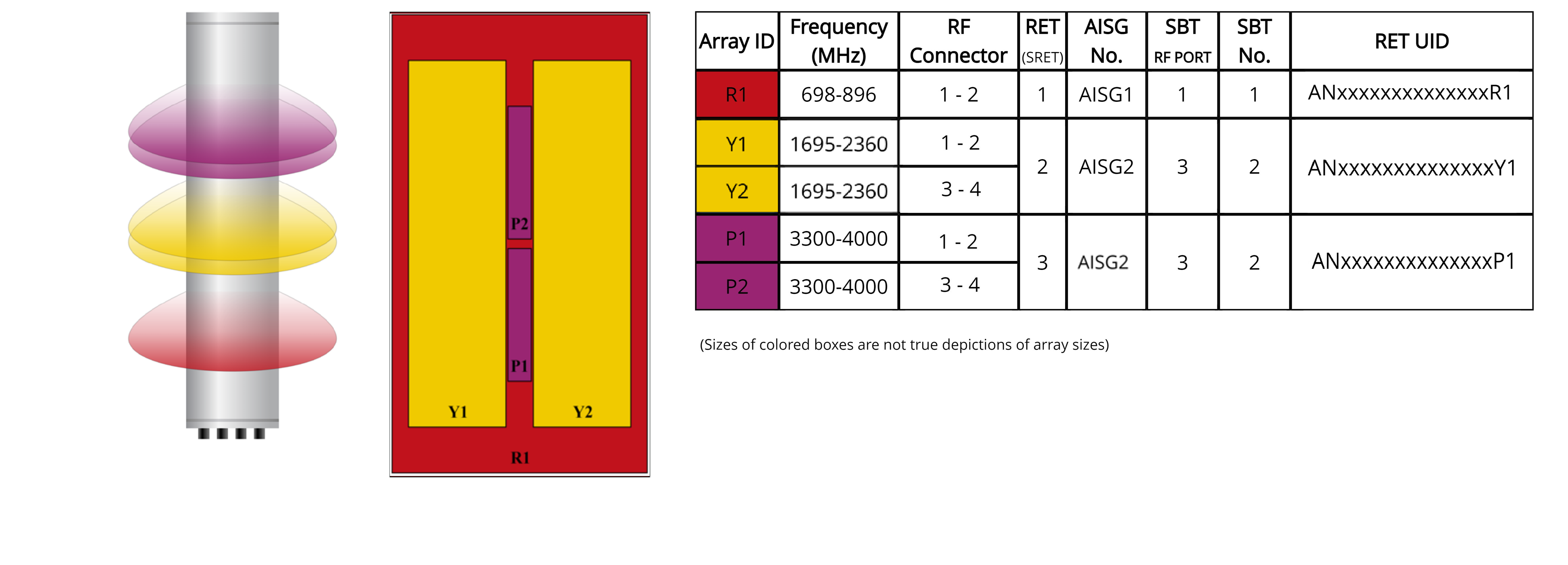
Array layout
| Click on image to enlarge. |
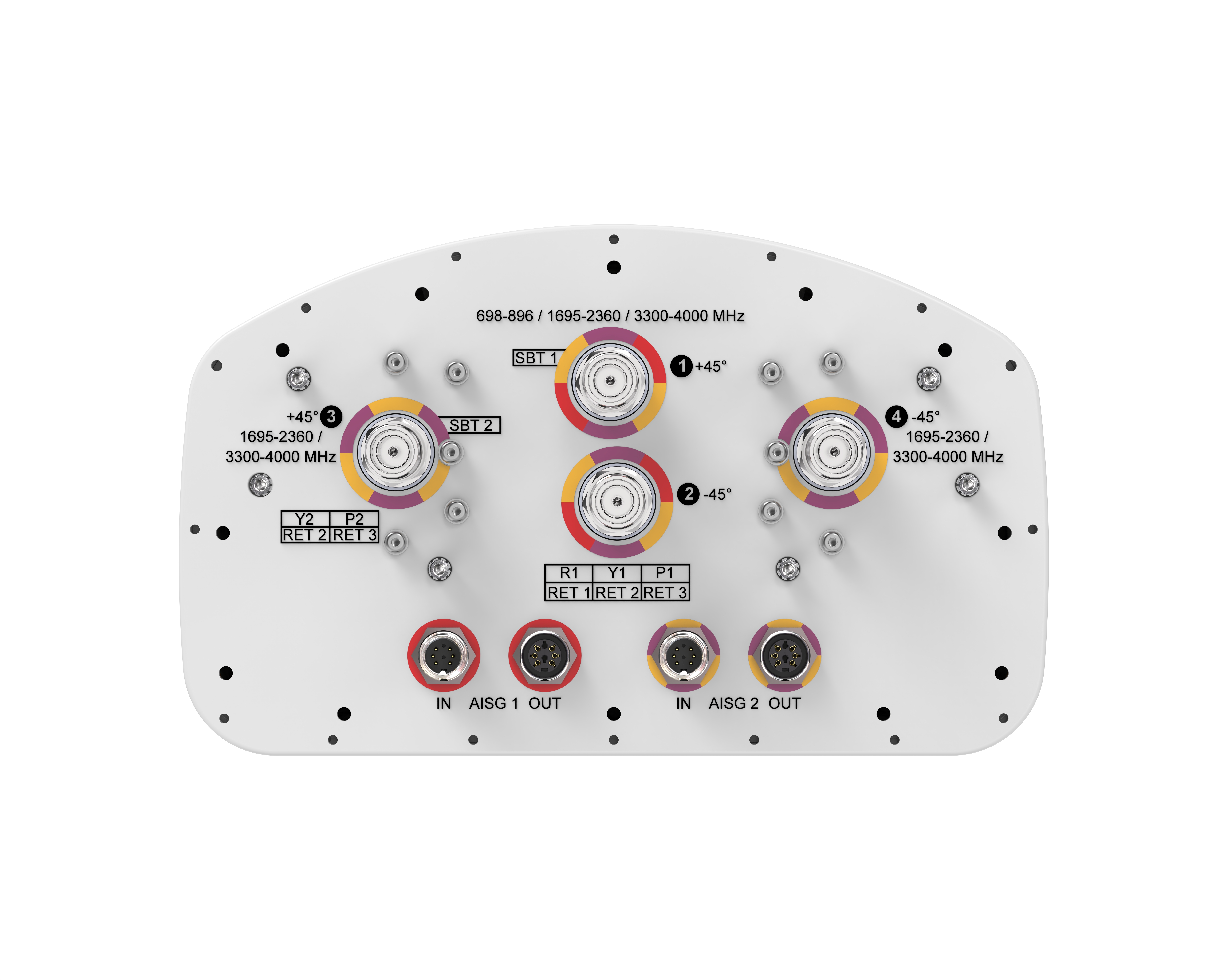
Port configuration
| Click on image to enlarge. |
Electrical specifications
| Impedance | 50 ohm |
| Operating Frequency Band | 698 – 896 MHz | 1695 – 2360 MHz | 3300 – 4000 MHz |
| Polarization | ±45° |
Electrical specifications
| R1 | R1 | Y1,Y2 | Y1,Y2 | Y1,Y2 | Y1,Y2 | P1,P2 | P1,P2 | P1,P2 | |
| Frequency Band, MHz | 698–806 | 806–896 | 1695–1880 | 1850–1990 | 1920–2200 | 2300–2360 | 3300–3550 | 3550–3700 | 3700–4000 |
| RF Port | 1-2 | 1-2 | 1-4 | 1-4 | 1-4 | 1-4 | 1-4 | 1-4 | 1-4 |
| Gain, Maximum, dBi | 15.300 | 15.200 | 18.500 | 18.600 | 18.600 | 18.100 | 18.300 | 17.900 | 18.600 |
| Gain, dBi | 15.0 | 14.9 | 18.1 | 18.4 | 18.2 | 17.8 | 17.9 | 17.5 | 18.1 |
| Beamwidth, Horizontal, degrees | 66 | 63 | 64 | 62 | 67 | 68 | 55 | 60 | 47 |
| Beamwidth, Vertical, degrees | 13.3 | 11.8 | 5.5 | 5.1 | 4.8 | 4.5 | 5.7 | 5.5 | 5.3 |
| Beam Tilt, degrees | 0–14 | 0–14 | 0–7 | 0–7 | 0–7 | 0–7 | 0–10 | 0–10 | 0–10 |
| USLS (First Lobe), dB | 15 | 16 | 17 | 17 | 16 | 18 | 16 | 17 | 18 |
| Front-to-Back Ratio at 180°, dB | 30 | 31 | 36 | 36 | 29 | 28 | 31 | 34 | 32 |
| CPR at Boresight, dB | 20 | 15 | 24 | 24 | 25 | 24 | 17 | 14 | 15 |
| Isolation, Inter-band, dB | 25 | 25 | 25 | 25 | 25 | 25 | 25 | 25 | 25 |
| VSWR | Return loss, dB | 1.5 | 14.0 | 1.5 | 14.0 | 1.5 | 14.0 | 1.5 | 14.0 | 1.5 | 14.0 | 1.5 | 14.0 | 1.5 | 14.0 | 1.5 | 14.0 | 1.5 | 14.0 |
| PIM, 3rd Order, 2 x 20 W, dBc | -153 | -153 | -153 | -153 | -153 | -153 | -145 | -145 | -145 |
| Input Power per Port at 50°C, maximum, watts | 250 | 250 | 150 | 150 | 150 | 150 | 150 | 150 | 150 |
Mechanical specifications
| Wind Loading @ Velocity, frontal | 306.0 N @ 150 km/h (68.8 lbf @ 150 km/h) |
| Wind Loading @ Velocity, lateral | 254.0 N @ 150 km/h (57.1 lbf @ 150 km/h) |
| Wind Loading @ Velocity, maximum | 590.0 N @ 150 km/h (132.6 lbf @ 150 km/h) |
| Wind Loading @ Velocity, rear | 311.0 N @ 150 km/h (69.9 lbf @ 150 km/h) |
| Wind Speed, maximum | 241 km/h (150 mph) |
Packaging and weights
| Width, packed | 380 mm | 14.961 in |
| Depth, packed | 295 mm | 11.614 in |
| Length, packed | 2110 mm | 83.071 in |
| Weight, gross | 38.3 kg | 84.437 lb |
Regulatory compliance/certifications
| Agency | Classification |
| ISO 9001:2015 | Designed, manufactured and/or distributed under this quality management system |
| UK-ROHS | Compliant |
General specifications
| Antenna Type | Sector |
| Band | Multiband |
| Color | Light Gray (RAL 7035) |
| Grounding Type | RF connector inner conductor and body grounded to reflector and mounting bracket |
| Performance Note | Outdoor usage |
| Radome Material | Fiberglass, UV resistant |
| Radiator Material | Low loss circuit board |
| Reflector Material | Aluminum |
| RF Connector Interface | 4.3-10 Female |
| RF Connector Location | Bottom |
| RF Connector Quantity, total | 4 |
Remote electrical tilt (ret) information
| RET Hardware | CommRET v2 |
| RET Interface | 4x 8 pin connector as per IEC 60130-9 Daisy chain in: Male / Daisy chain out: Female Pin3: RS485A(AISG_B), Pin5: RS485B(AISG_A), Pin6: DC 10~30V, Pin7: DC_ Return |
| RET Interface, quantity | 2 female | 2 male |
| Input Voltage | 10–30 Vdc |
| Internal Bias Tee | Port 1 | Port 3 |
| Internal RET | High band (1) | Low band (1) | Mid band (1) |
| Power Consumption, active state, maximum | 10 W |
| Power Consumption, idle state, maximum | 2 W |
| Protocol | 3GPP/AISG 2.0 |
Dimensions
| Width | 301 mm | 11.850 in |
| Depth | 181 mm | 7.126 in |
| Length | 1978 mm | 77.874 in |
| Net Weight, without mounting kit | 27.2 kg | 59.966 lb |
Electrical specifications
| Impedance | 50 ohm |
| Operating Frequency Band | 698 – 896 MHz | 1695 – 2360 MHz | 3300 – 4000 MHz |
| Polarization | ±45° |
Electrical specifications
| R1 | R1 | Y1,Y2 | Y1,Y2 | Y1,Y2 | Y1,Y2 | P1,P2 | P1,P2 | P1,P2 | |
| Frequency Band, MHz | 698–806 | 806–896 | 1695–1880 | 1850–1990 | 1920–2200 | 2300–2360 | 3300–3550 | 3550–3700 | 3700–4000 |
| RF Port | 1-2 | 1-2 | 1-4 | 1-4 | 1-4 | 1-4 | 1-4 | 1-4 | 1-4 |
| Gain, Maximum, dBi | 15.300 | 15.200 | 18.500 | 18.600 | 18.600 | 18.100 | 18.300 | 17.900 | 18.600 |
| Gain, dBi | 15.0 | 14.9 | 18.1 | 18.4 | 18.2 | 17.8 | 17.9 | 17.5 | 18.1 |
| Beamwidth, Horizontal, degrees | 66 | 63 | 64 | 62 | 67 | 68 | 55 | 60 | 47 |
| Beamwidth, Vertical, degrees | 13.3 | 11.8 | 5.5 | 5.1 | 4.8 | 4.5 | 5.7 | 5.5 | 5.3 |
| Beam Tilt, degrees | 0–14 | 0–14 | 0–7 | 0–7 | 0–7 | 0–7 | 0–10 | 0–10 | 0–10 |
| USLS (First Lobe), dB | 15 | 16 | 17 | 17 | 16 | 18 | 16 | 17 | 18 |
| Front-to-Back Ratio at 180°, dB | 30 | 31 | 36 | 36 | 29 | 28 | 31 | 34 | 32 |
| CPR at Boresight, dB | 20 | 15 | 24 | 24 | 25 | 24 | 17 | 14 | 15 |
| Isolation, Inter-band, dB | 25 | 25 | 25 | 25 | 25 | 25 | 25 | 25 | 25 |
| VSWR | Return loss, dB | 1.5 | 14.0 | 1.5 | 14.0 | 1.5 | 14.0 | 1.5 | 14.0 | 1.5 | 14.0 | 1.5 | 14.0 | 1.5 | 14.0 | 1.5 | 14.0 | 1.5 | 14.0 |
| PIM, 3rd Order, 2 x 20 W, dBc | -153 | -153 | -153 | -153 | -153 | -153 | -145 | -145 | -145 |
| Input Power per Port at 50°C, maximum, watts | 250 | 250 | 150 | 150 | 150 | 150 | 150 | 150 | 150 |
Mechanical specifications
| Wind Loading @ Velocity, frontal | 306.0 N @ 150 km/h (68.8 lbf @ 150 km/h) |
| Wind Loading @ Velocity, lateral | 254.0 N @ 150 km/h (57.1 lbf @ 150 km/h) |
| Wind Loading @ Velocity, maximum | 590.0 N @ 150 km/h (132.6 lbf @ 150 km/h) |
| Wind Loading @ Velocity, rear | 311.0 N @ 150 km/h (69.9 lbf @ 150 km/h) |
| Wind Speed, maximum | 241 km/h (150 mph) |
Packaging and weights
| Width, packed | 380 mm | 14.961 in |
| Depth, packed | 295 mm | 11.614 in |
| Length, packed | 2110 mm | 83.071 in |
| Weight, gross | 38.3 kg | 84.437 lb |
| Click on image to enlarge. |
| Click on image to enlarge. |
Regulatory compliance/certifications
| Agency | Classification |
| ISO 9001:2015 | Designed, manufactured and/or distributed under this quality management system |
| UK-ROHS | Compliant |
Documentation & downloads
Product information
Product specification
Product compliance documentation
Product information
Product specification
Related products & accessories
Included products
Base station antennas
-
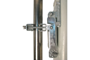
![]() BSAMNT-4 Wide Profile Antenna Downtilt Mounting Kit for 2.4 - 4.5 in (60 - 115 mm) OD round members. Kit contains one scissor top bracket set and one bottom bracket set.
BSAMNT-4 Wide Profile Antenna Downtilt Mounting Kit for 2.4 - 4.5 in (60 - 115 mm) OD round members. Kit contains one scissor top bracket set and one bottom bracket set.
Included products
Base station antennas
-
![]() BSAMNT-4 Wide Profile Antenna Downtilt Mounting Kit for 2.4 - 4.5 in (60 - 115 mm) OD round members. Kit contains one scissor top bracket set and one bottom bracket set.
BSAMNT-4 Wide Profile Antenna Downtilt Mounting Kit for 2.4 - 4.5 in (60 - 115 mm) OD round members. Kit contains one scissor top bracket set and one bottom bracket set.